E-ISSN:2583-2468

Research Article

Arduino Nano

Applied Science and Engineering Journal for Advanced Research

2025 Volume 4 Number 2 March
Publisherwww.singhpublication.com

Fault Detection in Underground Cable by using Arduino

Kharade JM1*
DOI:10.5281/zenodo.15386738

1* Jyoti M Kharade, Associate Professor, Department of Electrical Engineering, Annasaheb Dange College of Engineering & Technology, Ashta, Maharashtra, India.

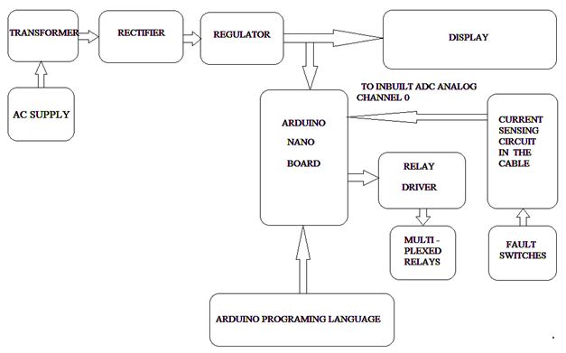
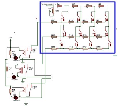
This paper presents the system to ascertain the length of faulty cable in kilometres by employing NANO ARDUINO outfit. In numerous Municipal fields, the underground cable method is employed. When faults or abnormalities occur due to any reason, it is difficult to rectify the quandary because of not perceiving the exact location of the fault. The proposed method is to localize the exact location or spot of the fault. The system employs the standard principle of Ohm’s Law i.e. the current changes depending upon the fault distance, where small voltage is employed at feeder end over series resistors. Consequently the voltage across the resistors alters which is calibrated in distance after feeding the data to inherent ADC of NANO ARDUINO outfit, and displayed on digital seven segment display. The hardware system is designed in such manner the series resistors, which are depicting cable length in kilometres, and short circuit fault formation is done with the switches at each comprehend kilometre to verify the correctness of the design. Hereafter, the work will be amplified with the application of capacitor in an AC system for finding the impedance, which will localize the open circuit in underground cable.

Keywords: arduino nano, underground fault, resistance, lcd

Corresponding Author How to Cite this Article To Browse
Jyoti M Kharade, Associate Professor, Department of Electrical Engineering, Annasaheb Dange College of Engineering & Technology, Ashta, Maharashtra, India.
Email:
Kharade JM, Fault Detection in Underground Cable by using Arduino. Appl Sci Eng J Adv Res. 2025;4(2):63-66.
Available From
https://asejar.singhpublication.com/index.php/ojs/article/view/143

Manuscript Received Review Round 1 Review Round 2 Review Round 3 Accepted
2025-02-11 2025-02-28 2025-03-25
Conflict of Interest Funding Ethical Approval Plagiarism X-checker Note
None Nil Yes 3.28

© 2025 by Kharade JM and Published by Singh Publication. This is an Open Access article licensed under a Creative Commons Attribution 4.0 International License https://creativecommons.org/licenses/by/4.0/ unported [CC BY 4.0].

Download PDFBack To Article1. Introduction2. Proposed
System
3. Hardware
Prototype
4. Result
Analysis
5. Future
Development
6. ConclusionReferences

1. Introduction

There are two methods for transmitting electricity, i.e. with the Overhead Transmission or with the Underground Transmission. Due to some benefits of underground cables like better advent, lesser maintenance, lower possibilities to impair because of direct lightning stroke or storms, lower voltage drop etc. But the higher installing expenses and insulation quandary at higher voltage applications make them arduous to adopt. Hence the underground method is practiced, where overhead method is an impossible to adopt. Generally in high density fields municipal authorities avoids overhead method due to safety reasons or due to the maintenance issue which is an impossible for such a field.

Whenever the abnormalities take place, the voltage of cable alters suddenly. Hence we execute the property to detect the fault. There are different approaches to determine the fault location in underground cables with different modes of analysis [1][2][5]. Md. Fakhrul Islam, et al have discussed the review of different techniques and guidelines with new developments if fault detection in detail [3].

A. Desirable Features

There are different techniques proposed for detection of underground cables faults [6] [7] [8] also for single phase and three phase [4]. Programs uploaded in ARDUINO NANO kit to detect faults from the underground cables. When a fault occurs in the underground cables, we can find out faults through ARDUINO controller kit. LCD display which displays the faults in Kilometre. In this system fault has created manually.

There are different types of cables available. Every cable has different resistance which depends upon the material used. The value of the resistance is depends upon the length of the cable. In here resistance is the leading role of the project. If any aberration takes place in the resistance, then changed value at the particular point for the voltage is known as Fault.

The main objectives of the work are as:-

1. To detect the faults & Abnormalities occurring in Underground Cables Using ARDUINO NANO.
2. To ascertain the length of faulty cable from the source station.

3. To analyse the type of Fault.

B. Problem Identification

Now a day’s technology has been advanced so rapidly that it has made human life more efficient and comfortable. So our projects and the system used in it is based upon control of devices from one particular location as it save the lot of time and effort. The system we have done approach towards automating the electrical power system with savings of the loss and better solution towards Underground cable faults [5].

2. Proposed System

The design is practiced as four resistances in series describing the cable i.e. R4 to 7, 8 to 11, 12 to 15 and 16 to 19 according to the given figure, four resistances for every phases and one for ground. The single switch represents one kilometer distance hence total four switches for four kilometers. Total three relays are utilized for continuous monitoring of lines. The fig. 1 shows the block diagram of proposed system for fault detection in underground cable with Closed Loop Operation. The switching operation is illustrated in Fig. 2.

asejar_143_01.JPG
Figure1:
Fault Detection in Underground Cable Closed Loop Operation


asejar_143_02.JPG
Figure 2:
Switching Operation

3. Hardware Prototype

The hardware implementation is carried out with the components:

A. Arduino Nano

The ARDUINO NANO is a compact, small and easily interfacing circuitry based on the AT mega 328.An embedded microcontroller is a small chip having a computer processor with all functioning and input/output ports including bus interfaces inbuilt in the device. Those functions minimize the external circuit and devices which are designed for final applications.

The improvements in ARDUINO NANO technology are such as cost effective faster and much more efficient for development and application.

The responsibilities that are taken by ARDUINO are:

1. Power distribution
2. Programming
3. Device Interfacing
4. System clocking

B. Filter

Capacitor filter as shown in fig. 3 is connected at the output terminal of bridge rectifiers to removes the ripples & smoothens the DC output until the mains voltages & load voltage is maintained constant (Fig. 4). Here simple capacitor filter is the basic type of power supply filter. The use of this filter is very low,

It can be used in following points –

1. Very High voltage
2. Low current power supply to cathode ray
3. For electron tube requires very less Load current from supply

asejar_143_03.JPG
Figure 3:
Basic circuit of Full Wave Rectifier circuit

4. Such type of filter will be used in circuits where the power supply ripple frequency is not critical & can be also high.

asejar_143_04.JPG
Figure 4:
Occurrence of Capacitor Charging & Discharging.

C. Relay

A Relay is the device which works on the electrical supply system. Basically relay uses an electromagnet to operate a switching mechanism mechanically as well as can used other principles also.

In Electrical circuit, relay is used to control a circuit by a low power signal and with complete electrical isolation between control & controlled circuits and in relay where several circuits must be controlled by one signal.

The Fig. 5 shows hardware implementation of proposed system. The general method, in which it is taken by inherent ADC of NANO ARDUINO outfit as explicated before. When we are going to operate any of the twelve switches as fault switches, then they make circumstances like line to ground (LG), line to line (LL) or triple line fault (LLL) according to switching actions. There is continuous monitoring which is provided by three relays during entire exercise. If fault takes place then the current start to flow and returns from ground and voltage drop developed over the resistor is taken in ARDUINO outfit after analog to digital conversion.


asejar_143_05.JPG
Figure 5:
Real Time Implementation

The digital output is displayed on seven segment display as in numbers of kilometre after occurrence B=3KM, then the fault is at three kilometres in B phase from base.

4. Result Analysis

The results are carried out creating the faults at different distances and measured minimum and maximum voltage during faults. The Table 1 shows the results for implemented hardware prototype.

Table: 1: Fault Detection Results

Sr. No.Distance (Km)Minimum Voltage (Volts)Maximum Voltage (Volts)
1.13.483.85
2.23.854.32
3.34.324.57
4.44.575

5. Future Development

This work can be extended for considering amount of time it saves. The projects we have undertaken can be used as key solution towards Underground cable fault at great level such as command on voltage, current, etc. our system is a small prototype by combining the ARDUINO andULN2003. Further it will be compact with the help of programming as well.

6. Conclusion

Basically identification of faults in underground cable is very difficult task. With the help of ANDUINO controller we can find out exact fault location up to 4KM. Thus by using this technique we can easily find and locate the exact point of fault or abnormality in underground cables. Once the faults occur in the cable, the display unit displays the exact fault location in a cable and displays which phase is affected in a cable & how long it’s affected. The Arduino exhibits several features over microcontroller such as fast operation and effective integration to other peripheral devices or systems.

References

1. Abhishek Pandey, & Nicolas H. Younan. (2010). Underground cable fault detection and identification via fourier analysis. IEEE.

2. H. Shateri. (2012). Impedance based fault location method for phase to phase and three phase faults in transmission systems. 11th IET International Conference on Developments in Power Systems Protection.

3. Md. Fakhrul Islam, et al. (2013). Locating underground cable faults: A review and guideline for new development. IEEE.

4. N.Gayathri, et al. (2018), Automatic underground cable fault detection with sms alert. International Research Journal of Engineering and Technology (IRJET), 05(02), 2077-2080.

5. P.S Pooja. (2015). Fault detection technique to pinpoint incipient fault for underground cables. International Journal of Engineering Research and General Science, 3(3), 1580-1587.

6. S. Navaneethan. (2001). Automatic fault location for underground low voltage distribution networks. IEEE Transactions on Power Delivery, 16(2), 346-351.

7. Xia Yang. (2008). Fault location of underground power cable using distributed parameter approach. IEEE Trans. Power System, 23(4), 1809-1816.

8. Yu Xiang. (2015). A bayesian approach for fault location in medium voltage grids with underground cables. IEEE Power and Energy Technology Systems Journal, 2(4), 116-124.

Disclaimer / Publisher's Note: The statements, opinions and data contained in all publications are solely those of the individual author(s) and contributor(s) and not of Journals and/or the editor(s). Journals and/or the editor(s) disclaim responsibility for any injury to people or property resulting from any ideas, methods, instructions or products referred to in the content.