9. Abdalla, I. I., Ibrahim, T., & Nor, N. M. (2018). Analysis of tubular linear motors for different shapes of magnets.Ieee Access,6, 10297-10310. DOI:10.1109/ACCESS.2017.2775863
10. Bianchi, N., Bolognani, S., Corte, D. D., & Tonel, F. (2003). Tubular linear permanent magnet motors: An overall comparison.IEEE transactions on industry applications,39(2), 466-475. DOI:10.1109/TIA.2003.809444
11. Leandro, M., Bianchi, N., Molinas, M., & Ummaneni, R. B. (2019, May). Low inductance effects on electric drives using slotless permanent magnet motors: A framework for
performance analysis. In2019 IEEE International Electric Machines & Drives Conference (IEMDC)(pp. 1099-1105). IEEE. DOI:10.1109/IEMDC.2019.8785241
12. Kang, G., & Nam, K. (2005). Field-oriented control scheme for linear induction motor with the end effect.IEE Proceedings-Electric Power Applications,152(6), 1565-1572. https://doi.org/10.1049/ip-epa:20045185
13. Cui, L., Zhang, H., & Jiang, D. (2019). Research on high efficiency V/f control of segment winding permanent magnet linear synchronous motor.IEEE Access,7, 138904-138914. DOI:10.1109/ACCESS.2019.2930047
14. Atencia, J., Martinez-Iturralde, M., Martinez, G., Rico, A. G., & Florez, J. (2003, June). Control strategies for positioning of linear induction motor: tests and discussion. InIEEE International Electric Machines and Drives Conference, 2003. IEMDC'03.(Vol. 3, pp. 1651-1655). IEEE. DOI:10.1109/IEMDC.2003.1210673
15. Yu, L., Huang, J., Luo, W., Chang, S., Sun, H., & Tian, H.Sliding-mode control for PMLSM position control—A review. Actuators 12, 31 (2023). https://doi.org/10.3390/act12010031
16. Shao, K., Zheng, J., Wang, H., Wang, X., Lu, R., & Man, Z. (2021). Tracking control of a linear motor positioner based on barrier function adaptive sliding mode.IEEE Transactions on Industrial Informatics,17(11), 7479-7488. DOI:10.1109/TII.2021.3057832
17. Liu, X., Wu, Q., Zhen, S., Zhao, H., Li, C., & Chen, Y. H. (2022). Robust constraint-following control for permanent magnet linear motor with optimal design: A fuzzy approach.Information Sciences,600, 362-376. https://doi.org/10.1016/j.ins.2022.03.083
18. Luo, M., Duan, J. A., & Yi, Z. (2023). Speed tracking performance for a coreless linear motor servo system based on a fitted adaptive fuzzy controller.Energies,16(3), 1259. https://doi.org/10.3390/en16031259
19. Liu, Z., Gao, H., Yu, X., Lin, W., Qiu, J., Rodríguez-Andina, J. J., & Qu, D. (2023). B-spline wavelet neural-network-based adaptive control for linear-motor-driven systems via a novel gradient descent algorithm.IEEE Transactions on Industrial Electronics
,71(2), 1896-1905. DOI:10.1109/TIE.2023.3260318
20. Wang, Z., Hu, C., Zhu, Y., He, S., Yang, K., & Zhang, M. (2017). Neural network learning adaptive robust control of an industrial linear motor-driven stage with disturbance rejection ability.IEEE Transactions on Industrial Informatics,13(5), 2172-2183. DOI:10.1109/TII.2017.2684820
21. Ding, R., Ding, C., Xu, Y., & Yang, X. (2022). Neural-network-based adaptive robust precision motion control of linear motors with asymptotic tracking performance.Nonlinear Dynamics,108(2), 1339-1356. https://doi.org/10.1007/s11071-022-07258-0
22. Cheema, M. A. M., & Fletcher, J. E. (2020).Advanced direct thrust force control of linear permanent magnet synchronous motor. Springer International Publishing. https://doi.org/10.1007/978-3-030-40325-6
Disclaimer / Publisher's Note: The statements, opinions and data contained in all publications are solely those of the individual author(s) and contributor(s) and not of Journals and/or the editor(s). Journals and/or the editor(s) disclaim responsibility for any injury to people or property resulting from any ideas, methods, instructions or products referred to in the content.


 ©
© 
 (1)
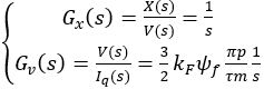
(1) is the magnetic flux generated by the permanent magnets of the rotor; ωr is the angular velocity converted from the linear velocity of the motor and is determined by the following expression:
 where v is the linear velocity of the rotor.
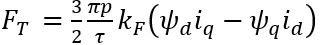 (2)
(2) are the magnetic fluxes generated by the permanent magnets on the d-axis and q-axis, respectively.
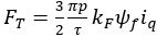 (3)
(3) (4)
(4) (5)
(5)
 (6)
(6) (7)
(7) (8)
(8)
 (9)
(9)
 (10)
(10)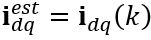 is the current at the k-th sampling time;
 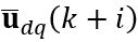 is the control signal for the next i-th step, with the prediction horizon N. The goal of the controller is to find an optimal control value. We select the value function in the following quadratic form:
 (11)
(11)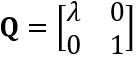 is a positive definite diagonal matrix, the coefficient
  is the weighting factor of the deviation in the value function J.
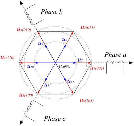
 . Therefore, a finite number of voltage vectors can be applied to the motor. In this paper, six fundamental vectors and six vectors created by pulse-width modulating the fundamental vectors to half their magnitude are used to form the vector set
  , as shown in Fig. 3.
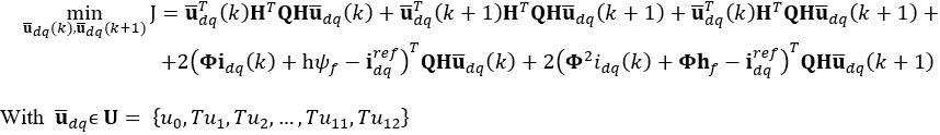 (12)
(12)