E-ISSN:2583-2468

Research Article

SolidWorks

Applied Science and Engineering Journal for Advanced Research

2025 Volume 4 Number 1 January
Publisherwww.singhpublication.com

Structural Simulation Analysis of a Hybridized Composite Pulley using SolidWorks Simulation Technique

Elvis E1*, Nwobi-okoye CC2, Ezechukwu VC3
DOI:10.5281/zenodo.14848687

1* Emifoniye Elvis, Mechanical Engineering Department, Delta State Polytechnic, Ogwashi-Uku, Nigeria.

2 Chiedozie Chukwuemeka Nwobi-okoye, Mechanical Engineering Department, Chukwuemeka Odumegwu Ojukwu University, Nigeria.

3 Vincent Chukwuemeka Ezechukwu, Mechanical Engineering Department, Chukwuemeka Odumegwu Ojukwu University, Nigeria.

This study explores the simulation and finite element analysis of a pulley hybridized composite reinforced (with silica sand and soda-lime glass) A36 grade steel and cast iron steel. SolidWorks simulation techniques were used in this study for the numerical analysis of stress-strain distribution and deformation under applied torque. A simulation study was carried out under the three different materials. The hybridized pulley had the highest strain and displacement of 5.63×10⁻² and 1.258×10⁻² for cast iron but the least weight of 1.8659N for the hybridized pulley. The material of choice based on displacement was cast iron pulley material, but based on weight and operational sufficiency, the hybridized pulley material can also be chosen because there were no large deviations from the strain and displacement analysis.

Keywords: composite, hybridized pulley, finite element, method, a36 steel, solidworks

Corresponding Author How to Cite this Article To Browse
Emifoniye Elvis, Mechanical Engineering Department, Delta State Polytechnic, Ogwashi-Uku, Nigeria.
Email:
Elvis E, Nwobi-okoye CC, Ezechukwu VC, Structural Simulation Analysis of a Hybridized Composite Pulley using SolidWorks Simulation Technique. Appl. Sci. Eng. J. Adv. Res.. 2025;4(1):41-49.
Available From
https://asejar.singhpublication.com/index.php/ojs/article/view/127

Manuscript Received Review Round 1 Review Round 2 Review Round 3 Accepted
2024-12-25 2025-01-13 2025-01-27
Conflict of Interest Funding Ethical Approval Plagiarism X-checker Note
None Nil Yes 2.19

© 2025 by Elvis E, Nwobi-okoye CC, Ezechukwu VC and Published by Singh Publication. This is an Open Access article licensed under a Creative Commons Attribution 4.0 International License https://creativecommons.org/licenses/by/4.0/ unported [CC BY 4.0].

Download PDFBack To Article1. Introduction2. Methodology3. Results
and Discussion
4. ConclusionReferences

1. Introduction

In order to overcome the limitations of single-reinforcement composites and polymers in the areas of high hardness values, wear resistance, heat resistance, and fire resistance, hybrid composites have recently been developed [1]. Recent studies on hybrid composites has focused on combining certain fibers to create composite materials. Among the many benefits of hybrid composites are their high tensile, flexural, elastic, impact energy, thermal stability, and resistance to abrasion and wear [2, 3, 4].

A pulley is a wheel that has a belt, chain, cable, cord, or other flexible rope attached to its rim. Pulleys can be used alone or in combination to transfer motion and energy. Sheaves are pulleys with rims that include grooves. Pulleys represent important components in various industries, bringing about the need for materials that can withstand significant mechanical stress, wear, and toughness [5]. Traditional materials such as steel cast iron, and plastics have been performing this function a long time but the emergence of composite materials opens a pathway to enhance performance while promoting sustainability.

In the Pulley application, the development and fabrication of an aluminum-reinforced composite creates a favorable way to overcome the disadvantages of conventional materials, such as reduced weight, improved toughness, and wear resistance [6]. Combining the distinct qualities of soda-lime glass, silica sand, and aluminum, the suggested hybridized composite provides a viable alternative that combines robustness, hardness, reduced wear, and toughness [7, 8].

Rounak et.al 2021) [9] Investigated using steel material, a composite material of Ti, Al, Cr, Mo, Zr (SS), and the ZnAC41A alloy in the design and numerical simulation of a spur gear using SolidWorks simulation. Material properties of all three materials, such as yield stress, ultimate tensile strength, Poisson ratio, and modulus of elasticity, were used for the formulation characterization in order to analyze Results of strain, stress, and deformation under a determined load. Findings from the study indicated that the composite material was characterized by a lighter weight and showed minimum deformation under load.

The 3D geometry of the disc-type cam and spherical follower of the IC engine was done in SolidWorks, and finite element analysis was performed in ANSYS Mechanical. Grey cast iron and structural steel were analyzed in terms of contact pressure and Hertzian contact stress. The results indicate that the factors in both materials showed a linear relationship, while the maximum values were low for grey cast iron. This material was better for the cam and follower pairs of motorbike engines. Strong data shows an agreement that verifies the prediction of the model on tribological properties [10].

Computer-aided analysis was used in the determination of the deformed and structural characteristics of leaf spring systems. The multiple-level steel leaf spring systems with dimensions of 10 by 7, 10 by 5, and 8 by 7 were investigated using ANSYS software. The resonance frequency values of 20 different mode shapes and overall deformation values obtained from the simulations are given in pressure values of 12.5 Pa, 25.0, and 37.5 Pa. The maximum deformations were observed within the given pressures in an 8-7 leaf spring system, as seen from the results [11].

AA6082 alloy was prepared by the stir casting method to investigate the mechanical properties of different weight percentages of reinforcement. Extensive mechanical testing, such as tensile, impact, flexural, and hardness studies, has been done. Finite element (FE) analysis of the composite pressure vessel of AMC was done using the geometrical dimensions of the steel vessel. Also, the stresses for the inside pressure of other materials were also evaluated. It was observed that MMCs fabricated vessels were evaluated to have relatively reduced weight compared to steel material [12].

The modelling of grain crushing process by Godara et al [13] using ANSYS and Solidworks in a created crusher. Speed distribution with a small range and a less number of movement of other type of crushers was concluded from the modeled result to produce the fields of speed distribution and the path of particle grain through the inside volume of the chopper. Results from modeling were in good correlation with experimental results

Modeling and analysis of connecting rods was performed by Oca et al [14] with FUSION 360 software, and ANSYS 2021 software. Design result and data evaluation was done using ANSYS.


With the help of proper technical documents, the design of the connecting rod was adequately done with standard specifications. Maximum Normal Stress and Maximum Equivalent (Von-Mises) Stress were less than yield strength from analysis study. Connecting rod material strength was evaluated to be 1.26 with a factor of safety of 3.406

A state-of-the-art fatigue propagation model to a new cohesive model for the initiation of fatigue, making use of initiation S-N curve data in predicting the cycles of delamination. A Mechanical APDL in ANSYS with user-defined cohesive element was developed that successfully predicted crack growth rates in fatigue propagation and successfully simulated test cases with multiple delamination in fatigue initiation and propagation. [15]

Maximum stress and deformation were determined and compared using SolidWorks; disc and six-spoke were flywheels were analyzed. Grey cast iron and S-glass fiber were used as material for the model for finite element analysis. The energy-storing capability of the thresher machine was enhanced through proper material selection and geometrical arrangement design for a flywheel. It was investigated that centrifugal loading on a cast iron flywheel with a solid disc results in larger levels of stress, but less deformation. [16]

The properties of the interface fiber and aluminum matrix using a two-dimensional planar FE model. From the simulation results, it was reported that the cohesive layer behaves almost exactly like the matrix during the linear elastic deformation before the occurrence of damage. Young's modulus and shear modulus values of the cohesive layer were assumed to be equivalent to those of the matrix material in the FE simulation for analyzing the debonding behavior of these MMCs. It was also observed that the cohesive layer concept for the interface can be utilized in determining the shear stress at which the damage initiates. [17]

In this study, silica sand and soda-lime glass-reinforced hybridized composite with steel and cast iron material were used for the analysis of the pulley material with SolidWorks simulation. Analysis includes stress, strain, deformation, and mesh. Results from the analysis were then used to make relative comparisons in terms of the chosen analysis.

2. Methodology

2.1 Material Properties

Table 1 represents the material properties of the cast iron, A36 steel, and the hybridized reinforced soda-lime and silica sand composite used for the production of the composite pulley.

The material used for designing the pulley was soda-lime glass, silica sand, and AA5058 aluminum. The existing pulley was made from A36 grade steel and cast iron. Table 1 also presents the magnitude of the properties presented in terms of Young's modulus of elasticity, yield strength, tensile strength, and Poisson ratio. All materials are assumed isotropic in nature.

Table 1: Properties of Pulleys Materials

PropertiesASTM A36 Steel PulleyCast Iron PulleyHybridized Pulley
Model TypeLinear Elastic IsotropicLinear Elastic IsotropicLinear Elastic Isotropic
Default Failure CriterionMax von Mises StressMax von Mises StressMax von Mises Stress
Yield Strength (N/m²)2.5e+0081.75e+0085.90178e+007
Tensile Strength (N/m²)4e+0082e+0089.519e+007
Elastic Modulus (N/m²)2e+0111.2e+0102.8557e+008
Poisson's Ratio0.260.250.33
Mass Density (kg/m³)785076002300

2.2 Parametric Analysis

The modeling of the pulley was done using SolidWorks modeling, finite element analysis, and simulation software. The specification of the pulley is presented in Table 2.

Table 2: Parameters used for Pulley Model

S/NparametersValueUnit
1Outer Diameter11.82mm
2Inner Diameter54.10mm
3Bore diameter11.82mm
4Key way8.61 * 2.61mm
5Belt groove diameter54.10mm
6V-belt angle30degree
7Face width of pulley21.21mm
8Pulley Width8.73mm

2.3 Simulation Criteria

The static simulation is derived from the design calculation of a shaft attached to the pulley as the drive rotates with a speed of 1500 rpm over a pulley diameter of 54.1 mm. The torque is then calculated to result in 318.3 Nm with a power of shaft 31.42 kW. These criteria and boundary conditions were used to prepare the simulation study. Table 3 is the table that presents all criteria and the magnitude of all relevant criteria needed for the simulation.

Table 3: Static Simulation Criteria

S/NCriteriaMagnitudeUnit
1Power transmitted through shaft31.42Kw
2Diameter of Pulley54.1mm
3Speed of rotation of shaft1500RPM
4Applied Torque318.3Nm
5Tangential Force on Pulley14.6N

2.4. Mesh Properties

The mesh parameters provided are good for a 3D finite element analysis, using a solid mesh type and standard meshing approach to balance resolution and computational efficiency. Disabling automatic transitions ensures uniform element sizes, which is good to avoid abrupt changes in density but requires manual refinement in critical areas. The mesh has a 4-point Jacobian with a high mesh quality setting, which will maintain accuracy with the linear element but would be higher if nonlinear problems were present. An element size of 4.35961 mm with a tolerance of 0.217981 mm balances between detail and the speed of processing, while a high-quality plot ensures that the result is numerically stable as represented in Table 4. Figures 1, 2, and 3 are the mesh plots for the three pulley models of steel, hybridized, and cast iron composites, respectively

Table 4: Mesh Information for Model Pulley

Mesh typeSolid Mesh
Mesher Used: Standard mesh
Automatic Transition: Off
Include Mesh Auto Loops: Off
Jacobian points4 Points
Element Size4.35961 mm
Tolerance0.217981 mm
Mesh Quality PlotHigh

asejar_127_01.JPG
Figure1:
Mesh Plot for Steel Pulley material

asejar_127_02.JPG
Figure 2:
Mesh Plot for Hybrid Pulley 

asejar_127_03.JPG
Figure 3:
Mesh Plot for Cast Iron Pulley Material


3. Results and Discussion

3.1 Stress Analysis of Pulley Materials

The static simulation of the pulley shown in Figure 4 showed that the maximum von Mises stress is 2.255 × 10⁷ N/m² near the inner edge of the hub, while for the outer parts, it is less. It must be noted that the calculated stresses are much below the material yield strength value of 5.902 × 10⁷ N/m², thus meaning the pulley, in this condition, is within its elastic limit and is safe from permanent deformation under applied conditions. Nonetheless, stress concentrations at the hub reveal promising spots for design refinement through radius fill-ins or geometry changes to achieve improved durability. The deformation scale is exaggerated for visualization and does not represent actual physical deformation.

The von Mises plot of the pulley has a minimum of 4.410e+03 N/m² and a maximum of 2.280e+07 N/m² as seen in figure 5, which is well below the yield strength of the material, 2.500e+08 N/m². Thus, this design is structurally safe under the applied load. The high-value stress regions are concentrated around the hub and on load-carrying surfaces of the pulley, with low-stress regions out on the outer rims. The deformation has been exaggerated by a factor of 44.84 to view it easily.

This von Mises stress analysis of the pulley in Figure 4 shows the highest stresses near the central hub and inner edges of the groove, with decreasing stresses toward the outer edges. The maximum stress (2.284×10⁷ N/m²) is well below the yield strength (1.75 × 10⁸ N/m²). That is, the design is safe under the current load. However, the local concentration of stress near the hub may require further inspection for possible fatigue.

asejar_127_04.JPG
Figure 4:
Stress Analysis of Hybridized Pulley

asejar_127_05.JPG
Figure 5:
Stress Analysis of Steel Pulley

asejar_127_06.JPG
Figure 6:
Stress Analysis on Cast iron Pulley


3.2 Displacement Analysis of all Model Pulley Materials

Figure 7 is an FEA results display in terms of the static loading analysis for the displacement distribution of the pulley. The displacements are in red at 1.258 mm, light blue indicates areas that see the least amount of displacement, and the overall distortion is amplified by a factor of 6.05591 for clarity. Such asymmetry means there could be non-uniform loading or non-uniform constraints: Confirmation of loading conditions, material properties, and boundary constraints will be necessary for further analysis.

The static displacement plot indicates that displacements vary within a very small range, from 1.000e-030 to 1.713e-003 mm, indicating that it deforms minimally and retains its structural integrity under the load applied. Maximum displacement is recorded on the outer rim, while its central hub exhibits no essential displacement due to its boundary conditions, which are fixed. The resultant deformation is amplified with a scale factor of 44.84. The results confirm the design's robustness, though material optimization in low-displacement areas near the hub could reduce weight if necessary, as depicted in figure 8.

Figure 9: Total displacement analysis of the pulley. The red regions display the maximum displacement, occurring at the outer edges. The displacement of the rigid central hub is minimal and shown as blue. The magnitude is 2.835×10⁻² mm at maximum. The small range of displacement could suggest that the pulley has not shown any loss of structural integrity under the load applied.

asejar_127_07.JPG

Figure 7: Dispalcement Analysis of Hybridized Pulley

asejar_127_08.JPG
Figure 8:
Displacement Analysis of Steel Pulley

asejar_127_09.JPG
Figure 9:
Displacement of Cast Iron Pulley

3.3 Strain Analysis on all Pulley materials

Figure 10 shows the static strain distribution of a pulley from an FEA study. The minimum and maximum strains are 1.600e-05 and 5.628e-02, respectively. In areas where the strain value is high, there may be possible failure points; this may be around the edges or where the load is applied. Where the strain value is low, the material is stable, as shown in the hub. The deformation scale has been amplified by 6.05591 times for viewability.


The color contours in this FEA in figure 11 result show the static strain distribution in a pulley, with strain concentrated around the central hub and along certain curved sections, as depicted by the red and orange regions of the color scale. Deformation has been exaggerated 448:24 to enhance visibility; the outer surfaces have little strain (blue areas). The results point to some possible stress concentration near the hub, also in agreement with similar study of Ezechukwu et al [18]

FEA analysis of the pulley in Figure 12 shows strain distribution under static loading, with maximum strain (1.259e-003) concentrated around the inner bore and hub, as indicated by green to yellow regions, while the outer rim and middle surfaces experience minimal strain (blue). The symmetrical distribution suggests balanced loading conditions, but the strain concentration at the hub may require design improvements. Figure 13 is the actual produced hybridized pulley composite from silica sand and soda-lime glass reinforcement accompanied by the steel pulley that served as the pattern in the production of the composite in a cylindrical blank before machining.

asejar_127_10.JPG
Figure 10:
Strain analysis of Hybrid Pulley

asejar_127_11.JPG
Figure 11:
Strain analysis of steel pulley   

asejar_127_12.JPG
Figure 12:
Strain Analysis of Cast Iron Pulley

asejar_127_13.JPG
Figure 13:
Steel and Hybridized Pulley

4. Conclusion

The final element analysis for the pulley model using measured parameters of young tensile strength modulus of elasticity,


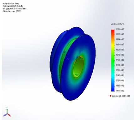
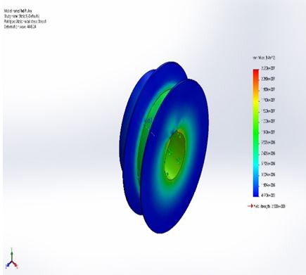
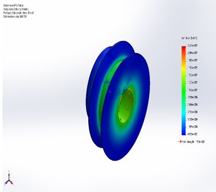
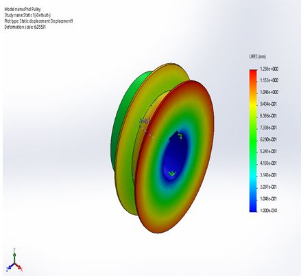
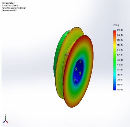
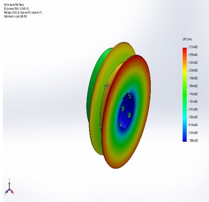
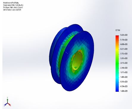
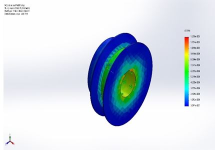
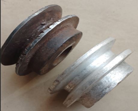
yield strength, and poison ratio for the three production (A36 grade steel material, cast iron material, and hybridized composite) within a torque level of 318.3 Nm and the same boundary conditions indicated sufficiency in service life operation conditions. The maximum von Mises stress, displacement, and strain of the three simulated pulley materials are presented in Table 5 below. The weight levels of the three materials used in the pulley are also presented in the table below, indicating that the hybridized pulley had the least weight compared to that of steel and cast iron.

Table 5: Summary from Simulation and Finite element analysis of Materials for Pulley

MaterialMax Von mises N/m2Displacement
(mm)
Max. Strain(mm)Weight(N)
A36 Grade Steel2.280e+0071.713e-0037.62E-056.3684
Cast Iron2.284e+0072.835e-0021.26E-036.1656
Hybridized Composite2.255e+0071.258e-0025.63E-021.8659

Author Contributions:All the authors contributed to the development of the work. All authors read and approved the final manuscript.

Declarations:Ethics approval and consent to participate This work does not include humans and animals and hence does not require ethical approval from any committee and does not require consent to participate in the research.

Consent for Publication: The authors give the publisher the consent to publish the work.

Competing Interests: The authors declare no competing interests.

References

1. Ezechukwu V. C. (2024). Hybridization effect on thermo-mechanical behaviour of epoxy/breadfruit seed shell ash particles and momordica angustisepala fiber composites for high-temperature devices application. Iconic Research and Engineering Journals, 7(11), 213-223.

2. Braide, T.K., Nwobi-Okoye, C.C., & Ezechukwu, V.C. Taguchi-Grey multi-response optimization of wear parameter of new nanocomposite formulation of Al–Si–Mg alloy reinforced with synthesis carbon nanotube and periwinkle shell nanoparticles. Int J Adv Manuf Technol, 120, 8363–8375. https://doi.org/10.1007/s00170-022-09163-7

3. Braide T. Kelsy, Chidozie Chukwuemeka Nwobi-Okoye, Vincent Chukwuemeka Ezechukwu, & Remy Uche. (2023). Multi objective optimization of novel Al-Si-Mg nanocomposites: A Taguchi ANN-NSGA-II Approach. Journal of Engineering Research. https://doi.org/10.1016/j.jer.2023.10.008

4. Obinwa,C C., Ezechukwu, V C., & Nwosu, A W. (2024). Optimization and analysis of mechanical properties (Tensile Strength) in a developed plantain hybrid fibre reinforced composite (PHFRC). International Journal of Engineering Research And Development, 20(12), 109-119.

5. Zhao, T., Qi, Z., & Wang, G. et al. (2024). An analysis method for rope-driven multibody systems with pulley blocks. J Mech Sci Technol, 38, 6471–6487. https://doi.org/10.1007/s12206-024-1105-x

6. Qianhui Fan, Huanqing Duan, & Xiaojun Xing. (2024). A review of composite materials for enhancing support, flexibility and strength in exercise. Alexandria Engineering Journal, 94, 90-103. https://doi.org/10.1016/j.aej.2024.03.048

7. Jamila S. Alzahrani, Z.A. Alrowaili, I.O. Olarinoye, Ebru Yılmaz, Fatih Çalıskan, Sultan Alomairy, & M.S. Al-Buriahi. (2024). Zircoborate glass-ceramic composite reinforced with aluminum oxynitride: Microstructural evolution, physical properties, and charged radiation attenuation analysis. Ceramics International, 50(20), Part A, 37633-37642. https://doi.org/10.1016/j.ceramint.2024.07.122

8. Jiaying Wei, Linyuwen Ke, Peng Wang, Weiwen Li, & Christopher K.Y. Leung. (2024). Microstructure, mechanical properties and interaction mechanism of seawater sea-sand engineered cementitious composite (SS-ECC) with Glass Fiber Reinforced Polymer (GFRP) bar. Composite Structures, 343, 118302. https://doi.org/10.1016/j.compstruct.2024.118302

9. Rounak Mahakul, Dhirendra Nath Thatoi, Sasanka Choudhury, & Pragyan Patnaik. (2021). Design and numerical analysis of spur gear using SolidWorks simulation technique. Materials Today: Proceedings, 41(2), 2021, 340-346.https://doi.org/10.1016/j.matpr.2020.09.554

10. Kumar Vardaan, & Paras Kumar. (2023). Tribological parameters analysis of cam and follower pair used in IC engine using ANSYS. Materials Today: Proceedings. https://doi.org/10.1016/j.matpr.2023.05.525


11. Mehmet Bahadır Çetinkaya,& Muhammed İşci. (2023). ANSYS based analysis of multi-level parabolic leaf spring systems. Alexandria Engineering Journal, 73, 109-121. https://doi.org/10.1016/j.aej.2023.04.043

12. Mohanavel, S. Prasath, M. Arunkumar, G.M. Pradeep, & S. Surendra Babu. (2021). Modeling and stress analysis of aluminium alloy based composite pressure vessel through ANSYS software. Materials Today: Proceedings, 37(2), 1911-1916. https://doi.org/10.1016/j.matpr.2020.07.472

13. Yiming Yan, Liqiang Zhang, Xiaorong Luo, Ronghu Zhang, Qinglu Zeng, & Shuai Jiang. (2024). Effects of grain crushing, ductile grain deformation, and grain packing texture on sandstone compaction: Implications from DEM numerical simulations. Geoenergy Science and Engineering, 237, 212803. https://doi.org/10.1016/j.geoen.2024.212803

14. S. Godara, Vinayak Brenia, Amit Kumar Soni, Rupender Singh Shekhawat, & K.K. Saxena. (2022). Design & analysis of connecting rod using ANSYS software. Materials Today: Proceedings, 56(4), 2022, 1896-1903. https://doi.org/10.1016/j.matpr.2021.11.166

15. Iñigo Urcelay Oca, Brian Lau Verndal Bak, Albert Turon, & Esben Lindgaard. (2024). An ANSYS user cohesive element for the modelling of fatigue initiation and propagationof delaminations in composite structures. Engineering Fracture Mechanics, 308, 110337. https://doi.org/10.1016/j.engfracmech.2024.110337

16. Kumar Vardaan, & Paras Kumar. (2022). Design, analysis, and optimization of thresher machine flywheel using Solidworks simulation. Materials Today: Proceedings, 56(6), 3651-3655. https://doi.org/10.1016/j.matpr.2021.12.348

17. Shashi Bahl, & Ashok Kumar Bagha. (2021). Finite element modeling and simulation of the fiber–matrix interface in fiber reinforced metal matrix composites. Materials Today: Proceedings, 39(1), 70-76. https://doi.org/10.1016/j.matpr.2020.06.160

18. Ezechukwu, V. C., Onyenanu, I. U., Ayadinuno, G., & Agwaziam, J. O. (2025). Structural simulation analysis of the developed hybrid of Momordica angustisepala fiber and Breadfruit seed-shell particles composites Bolted Flanges. IPS Journal of Engineering and Technology, 1(1), 13–20. https://doi.org/10.54117/ijet.v1i1.2

Disclaimer / Publisher's Note: The statements, opinions and data contained in all publications are solely those of the individual author(s) and contributor(s) and not of Journals and/or the editor(s). Journals and/or the editor(s) disclaim responsibility for any injury to people or property resulting from any ideas, methods, instructions or products referred to in the content.