E-ISSN:2583-2468

Research Article

TRIAC and Arduino

Applied Science and Engineering Journal for Advanced Research

2023 Volume 2 Number 1 January
Publisherwww.singhpublication.com

Study of Speed Control and Monitoring of Induction Motor using TRIAC & Arduino

Kumar S1*, Aman2, Vardhan K3, Kuldeep4
DOI:10.54741/asejar.2.1.1

1* Sandeep Kumar, Senior Lecturer, Department of EE, CDL Govt Polytechnic, Nathusari Chopta, India.

2 Aman, Student, Department of EE, CDL Govt Polytechnic, Nathusari Chopta, India.

3 Kriti Vardhan, Student, Department of EE, CDL Govt Polytechnic, Nathusari Chopta, India.

4 Kuldeep, Student, Department of EE, CDL Govt Polytechnic, Nathusari Chopta, India.

This project is proposed to control and monitor the speed of the single-phase induction motor by using the Arduino Uno. Arduino Uno is used to produce the pulse width modulation (PWM) signals. and the motor speed is control by using the driver and single-phase inverter circuits. And this project has reduced the harmonics and switching losses of the circuit. In this project have Arduino uno is used to increment and decrement the speed of the induction motor. The speed feedback is connected to Arduino Uno controller. The Arduino Uno transfers the speed signal through wifi.

Keywords: motor speed control, triac ac drive, ardunio, zero cross detector

Corresponding Author How to Cite this Article To Browse
Sandeep Kumar, Senior Lecturer, Department of EE, CDL Govt Polytechnic, Nathusari Chopta, , India.
Email:
Kumar S, Aman, Vardhan K, Kuldeep, Study of Speed Control and Monitoring of Induction Motor using TRIAC & Arduino. Appl. Sci. Eng. J. Adv. Res.. 2023;2(1):1-3.
Available From
https://asejar.singhpublication.com/index.php/ojs/article/view/38

Manuscript Received Review Round 1 Review Round 2 Review Round 3 Accepted
2023-01-12 2023-01-14 2023-01-25
Conflict of Interest Funding Ethical Approval Plagiarism X-checker Note
None Nil Yes 13.31

© 2023by Kumar S, Aman, Vardhan K, Kuldeepand Published by Singh Publication. This is an Open Access article licensed under a Creative Commons Attribution 4.0 International License https://creativecommons.org/licenses/by/4.0/ unported [CC BY 4.0].

Introduction

The Objective of this paper is controlling AC motor speed control using Arduino and TRIAC. Turning any electronic appliance on and off is easy by various automation projects in which control mechanism technique is used but many times we are required to control the AC power partially like controlling the intensity of light or the speed of a single phase motor.

For that, PWM technique. PWM is known as pulse width modulation, in this technique, the average voltage sent to the load is controlled by turning the switch between the input supply and load on & off at a fast rate, that is how it generates variable width pulses, which can help in controlling the speed of a fan. An Arduino generates these PWM signals.The ardunio used in the paper has been programmed using embedded python language.

Overview

As AC loads everywhere around us. In addition, most of the home appliances are supplied with the AC Power supply. There is lot of situations that we want to have full control over an AC load such as a Voltage control of a lamp, speed control of AC motor/ Fan, and so many other applications. The proper way to control 230v AC is through phase control with a Triac: the Triac then is fully opened, but only during a part of the sinus AC wave.
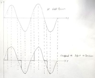
asejar_38_01.jpg
Figure 1:
Chopped AC Input to Drive

However, controlling an AC load is not as easy as controlling a DC load. The electronics circuit for both these applications is different. The AC mains with a sinusoidal wave has a frequency of 50Hz. To build an AC Drive the zero-crossing points (the points where the wave changes its polarity) are important.

To detect these points, we have to build a zero-crossing detector first. Similarly, we have to control the phase and cycle of the waveform. Since every component can’t tolerate 220V AC, so we need to isolate the circuit from 220V AC using some other component.

Proposed System

This paper provides a new speed control method of single-phase AC induction motor. It is available at high efficiency; with economical cost. AC drive is proficient of supplying a single-phase induction motor with PWM modulated sinusoidal voltage output. An ARDUINO Uno mostly used TRIAC phase angle, control drives. The circuit is capable of supplying single-phase induction motor with inductive or resistive load and with variable AC voltages.
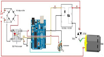
asejar_38_02.jpg
Figure 2:
Complete Circuit Diagram

It is comparable to TRIAC control, the voltage applied to the load can be changed from minimum to maximum value. A PWM technique has been used and it can be compared with phase angle control, which will be used for TRIAC, which produces considerably low higher order harmonics. Since the circuit, aimed at economical cost, medium powered applications, to get the output voltage waveform.

It can modulate mains AC voltage. As related with expensive converter, it needs low in number of active and passive power components. The drive accompanies TRIAC with PWM control. This control drive based on this recommended control procedure can be used in consumer as well as industrial products like fans, blowers, and washing machines etc.

The circuit works on the principle of PWM technique for speed control of an induction motor. When we want to increase or decrease the motor this project will be more useful. First to increase the motor increment switch is turned on and it can vary in steps and when the user want to decrement the speed of motor, decrement switch will be turned on.


These speeds are controlled by using TRIAC and Zero Crossing detector connected to circuit between microcontroller and induction motor. The TRIAC will control pulses of Ac supply input by using microcontroller input signal and also zero crossing detector.

The circuit is divided into 3 parts:

  • Zero Cross Detector Circuit
  • Phase/Angle Control Using Triac
  • The Arduino Code for changing delay in ms

Zero Cross Detector Circuit

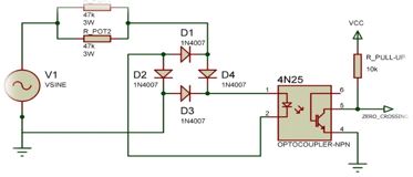
The AC voltage that we get from home supply is around 220*√2 or appx. 310 volts peak to peak or 220V RMS. The frequency is usually between 50 Hz.+-3% We have a positive part and a negative one so there will be a zero crossing, so we will have to detect that zero-cross since our pulse needs to be in phase with AC voltage.

asejar_38_03.jpg
Figure 3:
Circuit Diagram of Zero detector

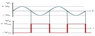
So, we have to detect when voltage passes from positive to negative or from negative to positive and synchronize our pulse with that so it will fire always in same spot. For that, we will use a full bridge rectifier. This will give output both positive and negative curves of AC wave.

asejar_38_04.jpg
Figure 4:
wave form showing zero cross

There are two 47 kilo-ohms resistors to limit current. And to separate high voltage side from low voltage side, we will use an EL817 optocoupler. In this way, there is no direct connection between 220V high voltage and 5V of Arduino.

Phase/Angle Control Using Triac

Using a component called TRIAC, we will control amount of time that this power is ON and OFF.

But before that, we need to understand the working of TRIAC. We are aware of the diode. When we put a single diode to an AC signal, we get a half-wave rectifier. With just one diode, the positive part of AC waveform remains & the negative part is chopped.

Conclusion

Speed control of the induction motors is one of the most trending topics nowadays, through this paper we found a new method controlling the speed by voltage variation of the induction motor by using Arduino Uno, this method shows a smooth control of the speed through control the output frequency by setting a code wrote in Arduino Uno coding language.

Future Scope

Our project “Speed monitoring of AC induction motor” is mainly intended controlling the AC Motor speed by using Microcontroller interfaces with touch screen and the speed displayed on LCD. The input is given by the user using touch screen to micro controller which in turn operates the AC motor speed. The input value from the touch screen to the micro controller will be checked and respective operation of that press will be performed like increasing or decreasing the speed of the AC motor. system can be extended by using wireless technology to operate the devices from longer distances.

References

1. P.S. Bimbhra. (2018). Power electronics. New Delhi: Khanna Publishers.
2. Depenbrock. (1975). Pulse width control of a three phase inverter with non sinusoidal phase voltages. in Proc. IEEEIAS Int. Semiconductor Power Conversion Conf., Orlaando, FL, pp. 389-398.
3. Chomat, & T.A. Lipo. (2003). Adjustable speed single phase IM drive with reduced number of switches. IEEE Trans. Ind. Appl., 39(3).
4. Bimal K. Bose. (2014). Modern power electronics and AC drives. Prentice Hall Publishers.
5. A K Ray, & K M Bhurchandi. (2012). Advanced micro processors and peripherals. Tata McGraw Hill Private Limited.
6. IEC 60050 (Publication date: 1990-10). Section 411-31: Rotation Machinery - General, IEV ref. 411-31-10: "Induction Machine - an asynchronous machine of which only one winding is energized".
7. Knight, Andy. (2012). Three-Phase induction machines. Hosted by University of Alberta.